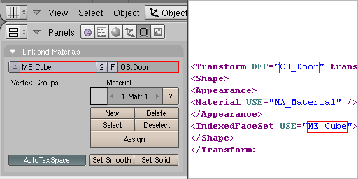
Exported Blender OB and ME names to X3D DEF and USE
Blender doesn't have a parametric 'primitive' concept, so every 3D object will be exported as an IndexedFaceSet or IndexedLineSet. Only the Blender 'mesh' type is currently supported. Blender surfaces, curves, meta and 3D text objects must be converted into meshes (Alt+C) before exporting them.
A named Blender object (OB) is exported as a (DEF) defined VRML/X3D Transform node. The named Bender mesh data (ME) is exported as a defined IndexedFaceSet or IndexedLineSet node.
Objects and their names are reused by Blender when instances are created with "Duplicated Linked" (Alt+D). For identical objects, try always to create instances instead of duplicates in order to optimize scene performance and file size.
To comply with VRML/X3D node naming rules, any digits at the beginning or illegal characters within the ME or OB name will be replaced with underscore (_) during export.

Exported Blender OB and ME names to X3D DEF and USE
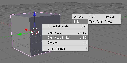
Originals and instances in Blender
Meshes can be exported as either an IndexedFaceSet (solid) or IndexedLineSet (wireframe), with IndexedFaceSet being the default. If you wish to export a mesh as an IndexedLineSet you must select "Wire" on either the "Draw" panel in "Object (F7)" or the "Material" panel in "Shading (F5)".
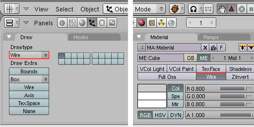
Creating IndexedLineSet using "Drawtype" or material property
You can export Blender meshes as a VRML PointSet by specifying a Drawtype of "Bounce".
You can control the export of single or double sided objects by toggling the "Double Sided" button in "Editing (F9)" on the "Mesh" panel. This option is activated by default in Blender.
To increase the performance of your real-time 3D scenes, you should always disable the "Double Sided" option for closed geometry.
If you have problems with the direction of faces/normals, you can check them easily by switching to the "UV Face Select" mode or by selecting "Draw Normals" on the "Mesh Tools" panel while in "Edit Mode".
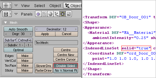
Control the export of one sided (solid="true") or double sided (solid="false")
In the export dialog you can specify whether to export normals or smoothing angles (VRML/X3D creaseAngles). Export normals enables smoothing at a polygon level whereas a simple smoothing angle output applies a creaseAngle to whole objects. Export normals is the default as it produces superior results (at the expense of file size).
If you wish to modify normals for smoothing export, you must enter "Edit Mode", select faces and click "Set Smooth" on the "Link and Materials" panel.
Alternatively, If you want to export smoothing angles on whole objects, select the object in "Object Mode", then in "Editing (F9)" on the "Mesh" panel enter the desired angle and hit the "Set Smooth" button on the "Link and Materials" panel.
At present, Blender is unable to accurately display custom smoothing angles in the 3D view, so for an accurate preview of the final output you should render an image.
BS Contact's rendering engine uses an optimized algorithm when a creaseAngle of 180 degrees (1 Pi radians) is specified, which improves the speed of rendering.
The "Auto Smooth" angle of Blender is limited to a maximum of 80 degrees, which is sometimes not enough, so if you set the "Auto Smooth" angle to 1 degree, a creaseAngle of 180 degrees (1 Pi radians) will be exported. Likewise, use an "Auto Smooth" angle of 2 for 90 degrees (1/2 Pi radians) and 3 for 135 degrees (3/4 Pi radians).
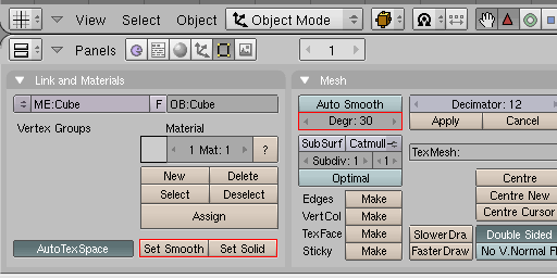
Exporting custom smoothing angle (creaseAngle) using "Set Smooth"
Mesh objects can be animated in "Object Mode" with Loc (translation), Rot (rotation) and Size (scale). Animation keys for meshes can be added by pressing "i" (insert key) in the "3D View" or using the auto keying feature of the "Timeline" window. You can control your animation in the "IPO Curve Editor".
[ return to top | return to overview ]